Hello! Welcome to visit the official website of Wuxi Driveshafts Co., Ltd. !

According as standard JB5513-91, use the following methods to select SWC-Ⅰseries and SWC series universal joint shafts. Please consult us for selecting other product series.
1.Universal joint shafts are selected according to the load features, calculated torques,bearing life, and operating speed.
2.The calculated torque is acquired from Formulas (1)、 (2) or (1)、(3):

Where: Tc = Calculated torque, N·m;
T = Theoretic torque, N ·m;
Pw = Driving power, kW;
PH = Driving power, hp;
n = Operating speed, rpm;
K = Service factors (See Table 10)
Service Factors K
| Service Factor Type |
Driven Equipment | K |
| Light shock load | Generators Centrifugal pumps Ventilators Wood handling machines Belt conveyers |
1.1~1.3 |
| Medium shock load | Compressors (multi-cyl.) Pumps (multi-cyl.) Small section mills Continuous wire mills Conveyer primary drives |
1.3~1.8 |
| Heavy shock load | Marine transmissions Transport roller tables Continuous tube mills Continuous working roller tables Medium section mills Compressors (single-cyl.) Pumps (single-cyl.) Mixers Presses Straightening machines Crane drives Ball mills |
2~3 |
| Extra heavy shock load | Paper machines Crane accessory drives Crushers Reversing working roller tables Reeling drives Scale breakers Blooming stands |
3~5 |
| Extreme shock load | Feed roller drives Plate shears | 6~15 |
3.Generally, universal joint shafts are selected according to the torque to be transmitted and the required bearing life. They can also be selected by checking their torque strengths or bearing life with relation to the requirements of the applicable equipment.
3.1 Checking the torsional strength using Formula (4), Tc ≤ Tn or Tc ≤ Tf or Tc ≤ TP ................ (4)
Tc = Calculated torque, N·m
Tn = Nominal torque, N·m (i.e., a theoretically calculated value under these pre-determined conditions: speed of shaft n≈10 rpm, deflection angle β = 3°, and a bearing life
LN = 5000 hours under even Icad).
Tf = Permissible torque according to the fatigue strength under alternating loads, N·m
TP = Permissible torque according to the fatigue strength under pulsating loads, N·m
TP=1.45Tf
3.2 Checking the bearing life Using Formula (5)
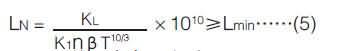
LN = Service life, hrs;
n = Operating speed, rpm;
β= Joint operating angle in operation, (°);
K1 = Prime motor factor
Electric motor: K1 = 1
Diesel generator: K1 = 1.2
KL = Bearing capacity factor (See Table 11);
Lmin = Min. bearing life, hrs;
T = Theoretic torque,kN·m
Bearing Capacity Factor
|
design
|
KL |
design
|
KL |
design
|
KL |
design
|
KL |
|
SWC-Ⅰ58
|
0.022×10⁻⁵
|
SWC160
|
0.16
|
SWC440
|
8.25×10³
|
SWCL225
|
9.79
|
|
SWC-Ⅰ65
|
0.012×10⁻⁴
|
SWC180
|
0.51
|
SWC490
|
2.145×10⁴
|
SWCL250
|
34.7
|
|
SWC-Ⅰ75
|
0.058×10⁻⁴
|
SWC200
|
1.47
|
SWC550
|
6.335×10⁴
|
SWCL285
|
106 |
|
SWC-Ⅰ90
|
0.048×10⁻³
|
SWC225
|
7.812
|
SWC620
|
0.13×10⁶
|
SWCL315
|
356 |
|
SWC-Ⅰ100
|
0.26×10⁻³
|
SWC250
|
28.2
|
SWCZ700
|
0.32×10⁶
|
SWCL350
|
938 |
|
SWC-Ⅰ120
|
0.26×10⁻²
|
SWC265
|
54.8
|
SWCZ750
|
0.75×10⁶
|
SWCL390
|
2323
|
|
SWC-Ⅰ150
|
2.65×10⁻²
|
SWC285
|
82.8
|
SWCZ800
|
1.06×10⁶
|
|
|
|
SWC-Ⅰ180
|
3.60×10⁻²
|
SWC315
|
279
|
SWCZ900
|
5.62×10⁶
|
|
|
|
SWC-Ⅰ200
|
1.03 |
SWC350
|
744
|
SWCZ1060
|
30.3×10⁶
|
|
|
|
SWC-Ⅰ225
|
1.89 |
SWC390
|
1860
|
|
|
|
|
4.When there are simultaneous horizontal andvertical angular misalignments on the universal jointshaft,the composite deflection angle is calculated using Formula (6):
Where:β= Composite deflection angle,(°);
β1= Horizontal deflection angle,(°);
β2= Vertical deflection angle,(°).
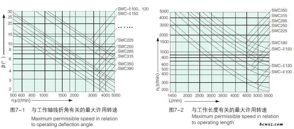
5.If the joint diameter of the shaft is 390mm or less,Formulas (7) and (8) should be used to check the maximum speed in addition to the considerations of torque and bearing life.

Where,nmax = Maximum operating speed,rpm;
[nβ] = Maximum permissible speed in relation to operating deflection angle,rpm.(See Figure 7-1)
[nL] = Maximum permissible speed in relation to operating length, rpm.(See Figure 7-2)
6.If the line speed of the shaft is over 7m/s, dynamic balancing test is requested, normally to a balancing accuracy between G16~G40. There are complex variables which effects the balancing grade. The customer's verification should be in a lower rank.